Saturday 6 July 2019

1950s Phoenix 283 Automatic

This was given to me a few days back. It had obviously not been used for years. The round rubber belt was broken, but it was so neglected that this was the least of its problems. It was also missing the foot controller, but it came with manuals and pattern cams! I was up for the challenge and have loads of the original foot controller.
It was also missing screws for the door!

The excellent Wernard motor had some issues: The capacitor (inside the motor housing) was  original (the only one I've ever seen in these motors), and just under what you can see in the photo the wires were bare and rubbing against the motor housing.
Capacitor is the silver thing at the top.

Plugging it in would have blown the circuit breaker.
The motor had to be completely disassembled to remove the capacitor (which doesn't have to be replaced), and I also found that the field winding insulation was cracked in three places (one was at the motor housing). I carefully removed the windings, cut the insulation off, then put on some heat shrink insulation, which was shrunk with a soldering iron before I reassembled the motor.

The test revealed that the foot controller wire was damaged and broken, so was replaced with a new lead. New lead means an un-needed power cord. I Wired it up and tested by bridging the wires and plugging it in when it's all back together and the motor runs at full speed.
The rest of it was just cleaning. I dusted off the cobwebs and cleaned the exterior with sewing machine oil. All old oil was also removed from metal with sewing machine oil and chrome polished.

I'm not in a hurry with this. My dad likes to work on the cabinets so he's been removing the 60-70 year old shellac and will be replacing it with varnish.

I'll update when the machine's finished. It won't look like new unless I paint it (the finish is faded, discoloured and chipped), but it'll certainly look a lot better than the poor sad thing I started with this morning, and I know it will sew like a new one. Wernard motors are excellent and more powerful than Singer motors. Also, their foot controllers use wire resistance, which means that they never go out of tune.
After a good clean, she's looking acceptable.

Sunday 30 June 2019

1970s Singer bobbin gear replacement

I was asked if I could fix someone's Singer 514 because it "didn't work".
The patient

A cursory inspection told me that the plastic bobbin drive gears had broken (needle moves and bobbin doesn't when the hand wheel is turned).
This is a very common problem now since the gears last about 40 years before they become brittle enough to break apart. It's probably why these machines don't have much value now, and most people will just throw them away rather than pay to replace them (particularly here in Australia where labour costs a lot). I don't know how long replacements will last, but I imagine you'd get 20 years at least.
I've done this job before, on my daughter's 498K Stylist in 2012. As I remember, the gears for her machine were much better quality than these, but it seems I can't get good ones now.
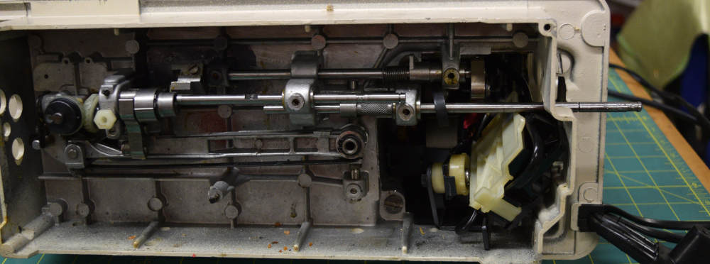
Where the bobbin gear lived and died

I told her the bad news. Although gears are available (Chinese made, and quite poor quality), the labour cost would exceed the machine's value. She was still keen (she had bought it new in 1973) so I ordered the gear set - they must be replaced as a set because the new ones are cut differently and won't mesh with the unbroken original, and even if they did mesh the unbroken one would break very soon too.
Pre-requisites to doing this job are:
1. You have the replacement gear set in front of you (I ordered them from Amazon).
2. You accept it will take a couple of hours if you haven't done it before, and do the whole job on the same day. You might be surprised how much you can forget in just a day.
3. You know how to time the hook.
4. Have some Singer gear grease on hand.
5. An appropriate Allen key and other tools to remove circlips.
6. Take photos as you go. These pictures are specific to the 514. They're all similar but don't count on them being identical.

Gear replacement

Disconnect the power (duh), remove the machine from its base and remove the bottom plate.

The bobbin mechanical components are then exposed
It's now obvious where the broken gear was.
Our task is to remove both of these shafts and replace the gears, but it's not as easy as you'd think. This is why it takes multiple hours instead of half an hour.
I had to remove the good gear first. Start by removing the circlip at the end nearest the motor (to the right in my pictures), then everything that's holding the shaft components on, including the white plastic gear on the left. You shouldn't need to force the shaft out.
Removal required an Allen key
Here's the shaft halfway out: The eccentrics for the feed dog should just sit there, held in by the rest of that mechanism.
All free and halfway out
The other shaft was tricky. It would not exit easily, and I had to remove the motor mounting in order to get it all the way out (to the right).
Almost there.
It's obvious from this photograph why the motor needs to be removed. The change from the old external motors to these quieter ones necessitated some compromise, and removing and replacing the motor was quite a struggle.
Once the two shafts are out, replace the gears and reassemble. Here are the new ones installed:
New gears installed
That big pointy bit of plastic fouls the movement of the other gear and causes a rough spot on the machine. You might be able to carefully remove a little to eliminate the rough spot, but I left it alone.
This is why I mentioned that the replacement gears are poor quality. It's not hard to make a copy of something this simple, but the people tasked with it still managed to screwed it up.
However, the machine does work acceptably now, where it didn't before, and the stitch quality is as good as it was before the original gear's demise.
After you've got everything back together you will need to correct the machine's timing, because you will definitely have changed to to unacceptable.

Feed timing

Make sure the feed dog is doing what it's supposed to be doing.
When the needle descends to the work, the feed dog will be moving downwards. If I remember correctly the offending plastic protrusion points towards a line etched into the feed timing eccentric (both of which can be seen in the picture above, taken before I'd replaced the latter's grub screw). Align these and you should see correct feed timing. If not, set it manually.

Hook timing

The settings are pretty universal for hook timing. You want it set up so that as the hook passes the needle, the needle has started to ascend and the needle's eye is 3/16" (2mm) below it, the needle position set to the centre. My friend Tammi has much more detail on this on her web site.
This is the setting for every sewing machine

Sunday 3 February 2019

Really easy pillow case with pocket.

I looked for really simple instructions on making a pillow case.
Someone I know will be teaching a child how to sew and a pillow case was the obvious first project. Two rectangles sewn together with a basic hem. Google didn't come up with anything simple or useful enough, so I looked at an acceptable existing one and after a few measurements came up with the instructions to duplicate it.

You'll need a 40" x 20" piece and a 32" x 20" piece. They don't have to be the same.

On one smaller edge (one 20" edge) of each piece, press ½" to the right side twice for the hem and stitch it.
Put the longer piece right side up and the shorter piece right side down on top, lining up the raw and of the shorter (20") edges.
Fold the extension of the bottom piece over the other so that the fold is as aligned as possible to the hem of the shorter piece.
Pin, stitch (½" seam allowance) and overlock (serge) the three edges. If your overlocker has four threads, you can skip the stitching. My overlockers are always older (as you'd expect) and are always the three thread variety.
Turn the right way and press.
After cutting, constructing this should take less than ten minutes per case.
I went with pure cotton, because it's incredibly easy to manage for a first project.
I made a pair. Shorter side is blue shirt fabric.

Internal Singer motor wiring

The machine was a Singer 201K3 but all Singers can have the same problem as this one.
When you come across an old Singer motor (1950s or older), it should be inspected thoroughly. If you have no idea what you're doing with electrical things, motors powered by mains voltage aren't a good way to start learning. Don't just plug it in and turn it on. While I'm on the subject, if the motor is hard wired (like the early ones), don't just switch it off, unplug it too. You'd be shocked to learn that the electrician crossed the neutral and live wires on that power point (pun intended).
Being someone who has quite a lot of experience with electrics, I removed the carbon brushes - remove them and put them somewhere so you can put them back in the exact same side and position as you removed them. If you put them back differently in any way, they won't make contact as well as before and the motor will be weak for a while. If they're short, you should replace them. They're only a few dollars and if you wear them out the springs will damage the commutator.
I then took the motor apart and the stator (the bit that doesn't move, also called the windings) wiring was as per this photo.
The wires (black and red)
In case it's not obvious, these wires are not fully insulated. I touched them a few times and the remaining insulation fell off. So where to now?
If you're not also extremely competent, confident and comfortable with electrical work, you have these options:

  1.  Take it to a small appliances shop and have it repaired.
  2. Have the motor reconditioned (re-wound) by a motor repair service (they do exist).
  3. Swap the motor with a known good one (or a new one, but be careful, new Chinese made motors are often as dangerous as the one above).
  4. Take the motor and light off, replace the hand wheel and pop it into a treadle cabinet.

Assuming you're all good to continue, you need to now make these two wires safe.
You will need a soldering iron, solder and some heat shrink tube insulation. If you don't have the latter, get some or you won't be able to complete this. Do not use electrical tape. It will melt off as soon as the motor gets warm, as will anything else. The heat shrink tubing needs a soldering iron's heat to shrink and will only melt if you burned it in a fire.
The rest of the wiring in the stator is held in place and not insulated with rubber, so we don't need to worry about it.
At the brush mounts, the wires are soldered to a copper ring, which is in turn soldered to the square brush contacts, which you can see in the picture is on either side of the hole at the end.
I was not able to remove the copper ring because of the amount of solder, so I cut it as close as possible.
Remove any remaining ' insulation'.
Now, cut a piece of the heat shrink insulation that will fit as snugly as possible over the bare wire and shrink on some new stuff (use a less hot part of your soldering iron and gently stroke it on all sides until it's hugging the bare wire).
Now solder it back onto where you cut it.
Do as Singer originally did and smother the whole end of the wire with solder. This is difficult because you need more hands than you were born with but you need to make sure these wires will never come loose.
It's unlikely they'll ever be pulled because only the rotor (armature) moves and you're going to ensure that it doesn't move anywhere near these two wires, but make sure it doesn't come off as you reassemble it.
Afterwards. Apologies for the fuzzy photo
I wasn't entirely happy about that millimetre of red wire that is exposed but there's absolutely no chance of it ever touching any conductor.
Repeat with the other wire then clean the commutator (the copper strips that come in contact with the carbon brushes).
Now reassemble the motor body, while watching the wires carefully as you put the end on. The wires will move differently now that you've changed the insulation. Make sure that the whole soldered area easily clears both the rotor's wiring coils and its contacts (the copper strips). I stress easily because the wires could settle slightly and move a little more when the motor warms up. Just imagine all that could go wrong and check that you've made sure it can't happen. It doesn't matter that it's a thousand times safer than before if it electrocutes someone because you didn't put enough solder on, left too much wire bare or used electrical tape. Do everything and your conscience will be happy.
So it was much more work than I expected, but I was extremely happy with the result. This motor should last many decades without anything more than the occasional set of carbon brushes.