Here's the problem: Singer used rubber insulation right up until the 1950s, so if you have just bought a machine of that vintage, you will probably find that the insulation has cracked off, exposing the live and neutral wires.
If you don't rewire it, you'll need to make sure you have circuit breakers and good life insurance.
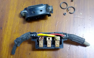
Just after Christmas last year a friend gave me her stash of old motors and foot controllers. She'd cut the wires on all of them so they definitely needed new wire anyway, but here's one I looked at this morning.
 | |||
| original wiring on both sides |
They are all supposed to be wired like this, so if you (like I have) come across an occasional machine that's different, you will find it's been fooled with by someone and my advice would be to change it back. It's safer, and much handier if you have a lot of machines.
The wire on the left was the power cord, the one on the right was the foot controller. These ones actually look in pretty good shape, because they're the later type with plastic insulation. In Singer wiring, Yellow is live and red is neutral.
In the next photo you can see the replacement. Incidentally, you should make the foot controller cord at least 1.2m (four feet) or it may not reach the floor. In Australian wiring live is Brown and neutral blue, so I put them back in the same order. The foot controller wiring is not important, since it isn't dependent on direction and there's no earthing involved. If you switch the live and neutral, you may notice a disturbing mains frequency vibration in your machine. Not necessarily dangerous but it feels it.
I have colour coded them in the picture to make it really obvious. Mains power live on the right, neutral on the left. Foot controller wires are left (with the mains live) and centre.
Do not forget to place the circular clips over the new wires before attaching them to the plug. Shape the wires by wrapping around a thin screwdriver and 'tin' them with solder so they keep this shape and ensure that strands of copper don't wander or break off.
 |
| Finished controller. |
When using my own machines, I make a habit of not unplugging the power plugs. It's easier and tidier to put the presser down on a small piece of fabric then the needle down and wrap both cords in opposite directions around the machine before placing the lid back.
And here's a wise saying I learned as a child "There are old electricians and there are bold electricians, but there are no old, bold electricians".

No comments:
Post a Comment